
Description
Feature
- Support onboard flashlight and DVP interface camera (Maximum resolution 1920*1088)
- Support AES / DES / 3DES / SHA / MD5 / CRC Encryption Engine
- Support STA / AP / STA + AP operating mode
- Support Smart Config/AirKiss one key match
- Support Serial port local upgrade and remote Firmware Upgrade (FOTA) function
- Support secondary development and integrate Windows and Linux development environment
- integrated video subsystem support to JPEG and YUV encode mode, also it supports to nv12 input format in off-line encode mode. (minimum resolution: 32 * 32 pixel, the maximum resolution: 1920 * 1088 )
Description
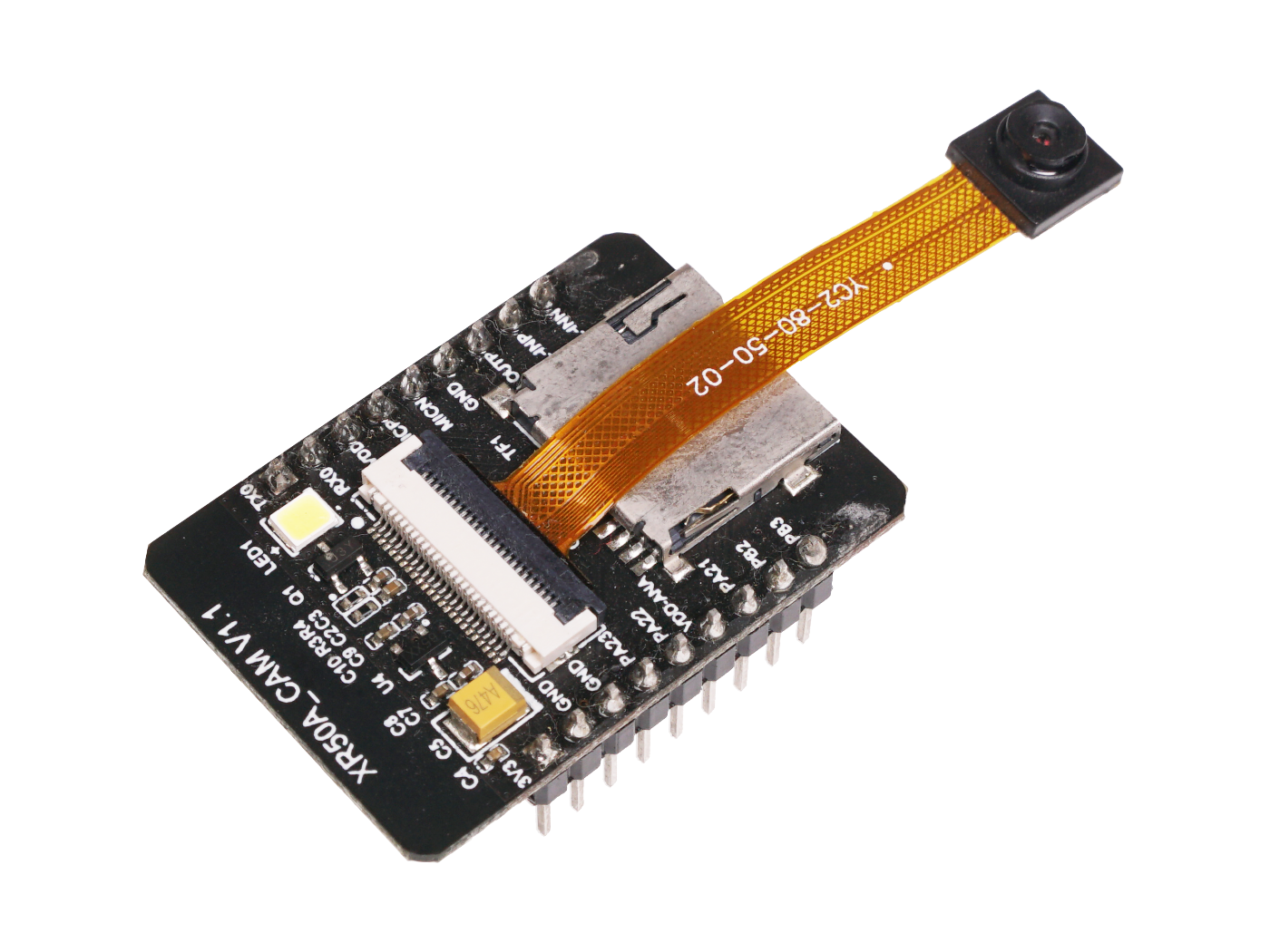
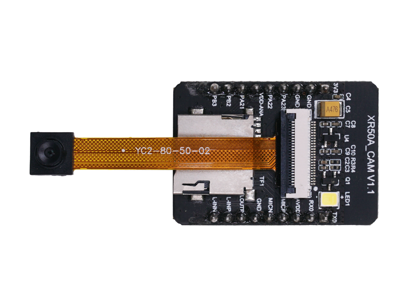
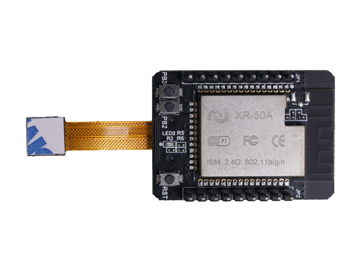
XR50A – CAM is a wireless image acquisition based on XR-50A-WIFI module development product, it has ARM Cortex-M4F 32 – bit micro MCU with the maximum frequency is 384MHZ, 416 KB SRAM, 160 KB ROM, 4MB PSRAM, AND 1024 bits efuse. It can be used as an image acquisition board or independent product development, XR50A – CAM hardware part contains a Camera interface port, reset buttons, TF card slot, the power indicator light, flashing light, XR-50A-WIFI module, it can be used for image acquisition and wireless transmission application interface, also it supports the microphone and speaker interface for audio collection and audio output.
Specifications
| Chip type | XR50_CAM |
|---|---|
| Encapsulation | DIP-18 |
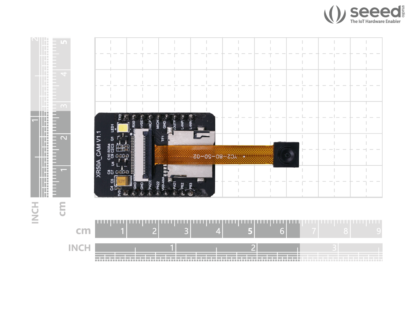
| Size | 38*27*11.5(-0.2 – +0.2)MM |
| SPI Flash | defult 32 Mbit |
| Support interface | UART / GPIO / PWM / CSI / MIC / Line-in / Speaker |
| I/O port | 5 |
| Series Rate | 9600 / 19200 / 38400 / 115200 / 921600 bps, up to 3Mbps |
| Spectral range | 2400 – 2483.5 MHz |
| Antenna form | On-board PCB antenna / IPEX extenal antenna |
| Transmitted power | 802.11b: 15 – 19 dBm (@ 11 Mbps) 802.11g: 13 – 17 dBm (@ 54 Mbps) 802.11n: 12 – 16 dBm (@ HT20, MCS7) |
| Receive sensitivity | CCK, 1 Mbps: -96dBm CCK, 11 Mbps: -91dBm 6 Mbps (1/2 BPSK): -91dBm 54 Mbps (3/4 64-QAM): -75 dBm HT20, MCS7 (65 Mbps, 72.2 Mbps): -73 dBm |
| Power dissipation (typical value) | Turn off flash light — Turn off camera: 48 mA Turn on flash light — Turn off camera: 111 mA Turn off flash light — Turn on camera: 108 mA Turn on flash light — Turn on camera: 156 mA |
| Security | WEP / WPA-PSK / WPA2-PSK / WPS 2.0 |
| Power supply | 3.3 V current > 600 mA |
| Working temperature | -40 °C – 85 °C |
| Storage environment | -65 °C – 150 °C, < 90% RH |
Dimensions
- 4 x 2.8 x 1 (cm)
Technical details
| No. | Pin | Function |
|---|---|---|
| 1 | TX0 | UART0_TX; JTAG_TMS; PWM4/ECT4; SWD_TMS; EINTB0 |
| 2 | RX0 | UART0_RX; JTAG_TCK; PWM5/ECT5; SWD_TCK; EINTB1 |
| 3 | AVDD | 2.8 V output, Support to external audio devices (CODEC) or mic-power |
| 4 | MICP | Coder Decoder ADC input p, microphone positive |
| 5 | MICN | Coder Decoder ADC input n, microphone negative |
| 6 | GND | ground connection |
| 7 | LOUTP | Coder Decoder DAC output p |
| 8 | LINEUP | Coder Decoder line-in input p |
| 9 | LINEN | Coder Decoder line-in input n |
| 10 | PB3 | SWD_TCK; JTAG_TDI; PWM7/ECT7; FLASH_HOLD/IO; EINTB3 |
| 11 | PB2 | SWD_TMS; JTAG_TD0; PWM6/ECT6; FLASH|_WP/IO2; EINTB2 |
| 12 | PA21 | UART2_RX; DMIC_CLK; PWM2/ECT2; SPI1_CLK; WUPIO7 |
| 13 | VDD_ANA | in-chip output 1.8 V |
| 14 | PA22 | UART2_TX; DMIC_DATA; PWM3/ECT3; SPI1_CS0; WUPIO8; EINTA22 |
| 15 | PA23 | EXT_DCDC_PUP; FEM_CTRL1; FEM_CTRL2; WUPIO9; EINTA23; (Default is not mean high-level signal) |
| 16 | GND | Ground connection |
| 17 | GND | Ground connection |
| 18 | 3V3 | Power supply 3.3 V |
Reviews
There are no reviews yet.