
Description
NOTE: It is recommended to use the upgraded version, RPLiDAR A2M6 360 Degree Laser Scanner Kit – 18M Range as your alternative choice (unit price $499).

Introduction
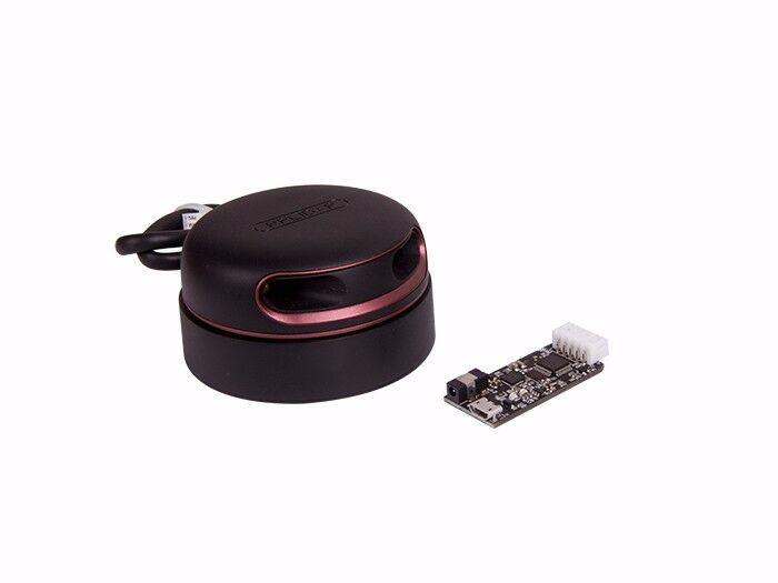
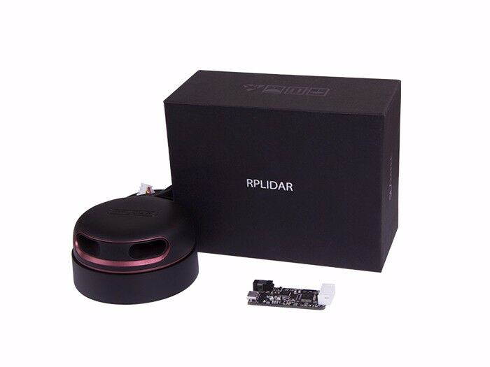
The RPLIDAR A2 is the next generation low cost 360 degree 2D laser scanner (LIDAR) solution developed by SLAMTEC. It can take up to 4000 samples of laser ranging per second with high rotation speed. And equipped with SLAMTEC patented OPTMAG technology, it breakouts the life limitation of traditional LIDAR system so as to work stably for a long time.
RPLIDAR A2M5/A2M6 is the enhanced version of 2D laser range scanner(LIDAR). The system can perform 2D 360-degree scan within a 16-meter range. The generated 2D point cloud data can be used in mapping, localization and object/environment modeling.
The typical scanning frequency of the RPLIDAR A2 is 10hz (600rpm). Under this condition, the angular resolution will be 0.9°. And the actual scanning frequency can be freely adjusted within the 5-15hz range according to the requirements of users.
The RPLIDAR A2 adopts the low cost laser triangulation measurement system developed by SLAMTEC, which makes the RPLIDAR A2 has excellent performance in all kinds of indoor environment and outdoor environment without direct sunlight exposure. Meanwhile, before leaving the factory, every RPLIDAR A2 has passed the strict testing to ensure the laser output power meet the standards of FDA Class I.
System connection
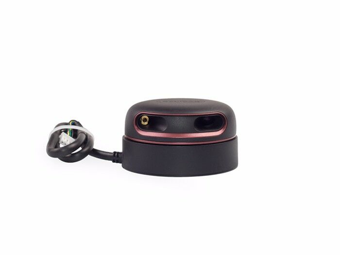
The RPLIDAR A2 consists of a range scanner core and the mechanical powering part which makes the core rotate at a high speed. When it functions normally, the scanner will rotate and scan clockwise. And users can get the range scan data via the communication interface of the RPLIDAR and control the start, stop and rotating speed of the rotate motor via PWM.

The RPLIDAR A2 comes with a rotation speed detection and adaptive system. The system will adjust the angular resolution automatically according to the actual rotating speed. And there is no need to provide complicated power system for RPLIDAR. In this way, the simple power supply schema saves the BOM cost. If the actual speed of the RPLIDAR is required, the host system can get the related data via communication interface.
The detailed specification about power and communication interface can be found in the following sections.
Mechanism
The RPLIDAR A2 is based on laser triangulation ranging principle and adopts the high-speed vision acquisition and processing hardware developed by SLAMTEC. The system ranges more than 4000 times per second. 
During every ranging process, the RPLIDAR emits modulated infrared laser signal and the laser signal is then reflected by the object to be detected. The returning signal is then sampled by vision acquisition system in RPLIDAR and the DSP embedded in RPLIDAR starts processing the sample data and outputs distance value and angle value between object and RPLIDAR via communication interface.
When drove by the motor system, the range scanner core will rotate clockwise and perform the 360-degree scan for the current environment.

Safety and Scope
The RPLIDAR A2 system uses a low power infrared laser as its light source, and drives it by using modulated pulse. The laser emits light in a very short time frame which can ensure its safety to human and pets, and it reaches Class I laser safety standard.

The modulated laser can effectively avoid the interference from ambient light and sunlight during ranging scanning process, which makes RPLIDAR work excellent in all kinds of indoor environment and outdoor environment without sunlight.
Data Output
During the working process, the RPLIDAR will output the sampling data via the communication interface. And each sample point data contains the information in the following table. If you need detailed data format and communication protocol, please contact SLAMTEC.
Figure 1 – 4 The RPLIDAR Sample Po int Data Information
| Data Type | Unit | Description |
| Distance | mm |
Current measured distance value between the rotating core of the RPLIDAR and the sampling point |
| Heading | degree | Current heading angle of the measurement |
| Start Flag | (Bool) | Flag of a new scan |
| Checksum | The Checksum of RPLIDAR return data |

The RPLIDAR outputs sampling data continuously and it contains the sample point data frames in the above figure. Host systems can configure output format and stop RPLIDAR by sending stop command. For detailed operations please contact SLAMTEC.
High Speed Sampling Protocol and Compatibility
The RPLIDAR A2 adopts the newly extended high speed sampling protocol for outputting the 4000 times per second laser range scan data. Users are required to update the matched SDK or modify the original driver and use the new protocol to use the 4000 times per second mode of RPLIDAR A2. Please check the related protocol documents for details.
The RPLIDAR A2 is compatible with all the communication protocols of previous versions. Users can directly replace the previous RPLIDAR with RPLIDAR A2 and use it in the original system. But in this scenario, the RPLIDAR A2 will work in compatible mode and the system will take range 2000 times per second.
Application Scenarios
The RPLIDAR can be used in the following application scenarios:
-
General robot navigation and localization
-
Environment scanning and 3D re-modeling
-
Service robot or industrial robot working for long hours o Home service /cleaning robot navigation and localization
-
General simultaneous localization and mapping (SLAM)
-
Smart toy’s localization and obstacle avoidance
Specification
Measurement Performance
-
For Model A2M5/A2M6 Only
Figure 2 – 1 RPLIDAR Performance
| Item | Unit | Min | Typical | Max | Comments |
| Distance Range | Meter(m) | 0.2 | – | 16 | Based on white objects with 70% reflectivity |
| Angular Range | Degree | – | – | – | |
| Distance Resolution | mm | – | <0.5 | – | <1.5 meters |
| <1% of the distance | All distance range* | ||||
| Angular Resolution |
Degree |
0.45 | 0.9 | 1.35 | 10Hz scan rate |
| Sample Duration | Millisecond(ms ) | – | 0.25 | – | – |
| Sample Frequency | Hz | 2000 | 4000 | 4100 | |
| Scan Rate | Hz | 5 | 10 | 15 | The rate is for a round of scan. The typical value is measured when RPLIDAR takes 400 samples per scan |
Note: the triangulation range system resolution changes along with distance.
Laser Power Specification
-
For Model A2M5/A2M6 Only
Figure 2 – 2 RPLIDAR Optical Specification
| Item | Unit | Min | Typical | Max | Comments |
|
Laser wavelength |
Nanometer(nm) | 775 |
785 |
795 | Infrared Light Band |
| Laser power | Milliwatt (mW) | – | 3 | 5 | Peak power |
| Pulse length | Microsecond(us) | 60 | 87 | 90 | – |
| Laser Safety Class | – | – | FDA Class I | – | – |
Note: the laser power listed above is the peak power and the actual average power is much lower than the value.
Optical Window
To make the RPLIDAR A2 working normally, please ensure proper space to be left for its emitting and receiving laser lights when designing the host system. The obscuring of the host system for the ranging window will impact the performance and resolution of RPLIDAR A2. If you need cover the RPLIDAR A2 with translucent materials or have other special needs, please contact SLAMTEC about the feasibility.

You can check the Mechanical Dimensions chapter for detailed window dimensions.
Coordinate System Definition of Scanning Data
The RPLIDAR A2 adopts coordinate system of the left hand. The dead ahead of the sensors is the x axis of the coordinate system; the origin is the rotating center of the range scanner core. The rotation angle increases as rotating clockwise. The detailed definition is shown in the following figure:

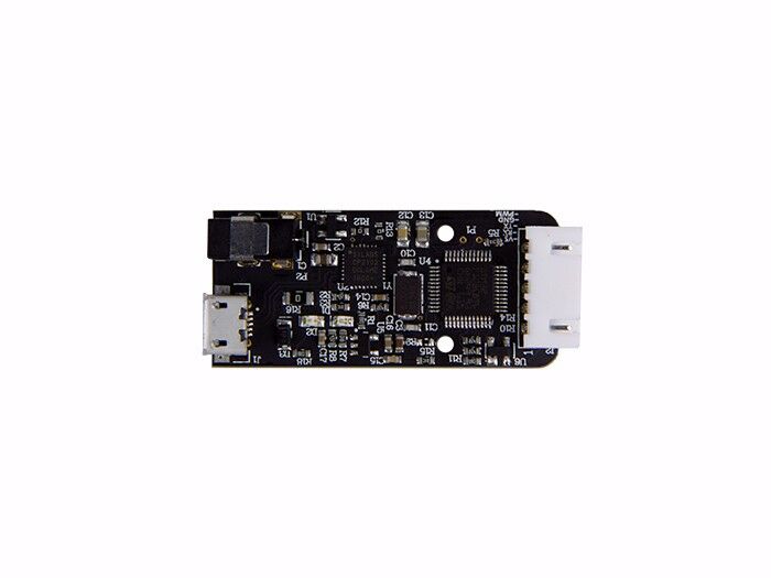
Communication interface
The RPLIDAR A2 uses separate 5V DC power for powering the range scanner core and the motor system. And the standard RPLIDAR A2 uses XH2.54-5P male socket. Detailed interface definition is shown in the following figure:

Figure 2 – 6 RPLIDAR External Interface Signal Definition
| Color | SignalName | Type | Description | Min | Typical | Max |
| Red | VCC | Power | Total Power | 4.9V | 5V | 5.5V |
| Yellow | TX |
Output |
Serial port output of the scanner core | 0V | 3.3V | 3.5V |
| Green | RX |
Input |
Serial port input of the scanner core | 0V | 3.3V | 3.5V |
| Black | GND | Power | GND | 0V | 0V | 0V |
| Blue | MOTOCTL | Input | Scan motor /PWM Control Signal (active high, internal pull down) | 0V | 3.3V | 5V |
Power Supply Interface
RPLIDAR A2 takes the only external power to power the range scanner core and the motor system which make the core rotate. To make the RPLIDAR A2 work normally, the host system needs to ensure the output of the power and meet its requirements of the power supply ripple.
-
For Model A2M5/A2M6 Only
Figure 2 – 7 RPLIDAR Power Supply Specification
| Item | Unit | Min | Typical | Max | Remark |
| Power Voltage | V | 4.9 | 5 | 5.5 | If the voltage exceeds the max value, it may damage the core |
| Power Voltage Ripple | mV | – | 20 | 50 | High ripple may cause the core working failure. |
| System Start Current | mA | – | 1200 | 1500 | The system startup requires relatively higher current. |
| Power Current | mA | TBD | 200 | 220 | 5V Power,power off |
| TBD | 450 | 600 | 5V Power,power on |
For more technical details, please visit the file below.
Reviews
There are no reviews yet.